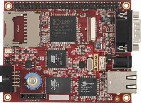
Ethernut 3.0 Rev-E
This board was replaced by Ethernut 3.1 Rev-D in October 2009.

Documents
Hardware References
Ethernut 3.0 Rev-E Hardware User's Manual
including all schematics.
Ethernut 3 Memory Map
Ethernut 3 memory layout.
Ethernut 3 CPLD
A detailed description of the CPLD registers.
enut30e.zip
Eagle 4.11 schematic and board file.
Programming
Nut/OS on Ethernut 3
How to install Nut/OS with a cross compiler and try a few sample applications on Ethernut 3.
JTAG Interface
Introduction to Ethernut 3 JTAG programming. Additionally describes how to
restore the TFTP Boot Loader.
OpenOCD and Ethernut 3
How to use OpenOCD with Ethernut 3 and Turtelizer 2.
Booting Ethernut 3
explains in detail how to get your Ethernut 3 application running after power-up.
NPL Upgrade
How to upgrade the CPLD logic. It explains how to build and upload a new contents for
the CPLD easily within seconds and without any special programming adapter.
Clock
An introduction to the programmable clock chip used on Ethernut 3.0 Rev-D and
Rev-E.
RTC (3.0)
An introduction to the realtime clock and calendar chip used on Ethernut 3.
Changes Compared to Version 3.0 Rev-D
Revision E fixes known bugs of it predecessor revision D and provides minor enhancements:
- RoHS conformant version.
- Lead free Taimag RJLD-043TC RJ45 with integrated magnetics replaces the leaded Falco LJ1003.
- Double layer capacitor increased from 0.33F to 0.47F.
- CPU clock fed from CLKB output of the PLL. This enables glitch free dynamic clock switching.
- Additional open drain drivers to the IOWAIT outputs of the CPLD and the DM9000E.
- X1286 with 32k EEPROM replaces the X1226, which had 512 Bytes EEPROM only.
- Pin 60 of IC2 (DM9000E) connected to pin 61. Now the link LED is lit at 10 and 100 MBit connections.
- Pin 4 of IC8 (LT1616) connected to pin 5.
- Yellow LED for the link indicator, and green LED for activity. This conforms to Ethernut 1 and 2.
- An additional pull-down had been added to force the Ethernet Controller into 16-bit mode after power-up.
Rev-E Schematics
Known problems:
-
The WP pin of the MMC socket had been routed to the wrong pad (CH2). Thus, it is not possible to determine, if the write protection of an SD Card had been enabled or disabled. Furthermore, when inserting cards with write protection enabled, shield and digital ground will be shortcut. There is no easy way to fix this.
-
It has been reported that the board fails when inserting SD Cards with 2 GB or larger capacity. A glitch of a few nanoseconds had been observed on the 3.3V power line. Adding a 10uF capacitor in parallel to C5 (470nF) seems to solve the problem.
