
Ethernut 2
General Hardware Documentation
Check the
I/O Port List
and the
Memory Map
for attaching external hardware to Ethernut 2.
Using RS-485 with Ethernut 2
Provides jumper setting and cabling info plus sample software.
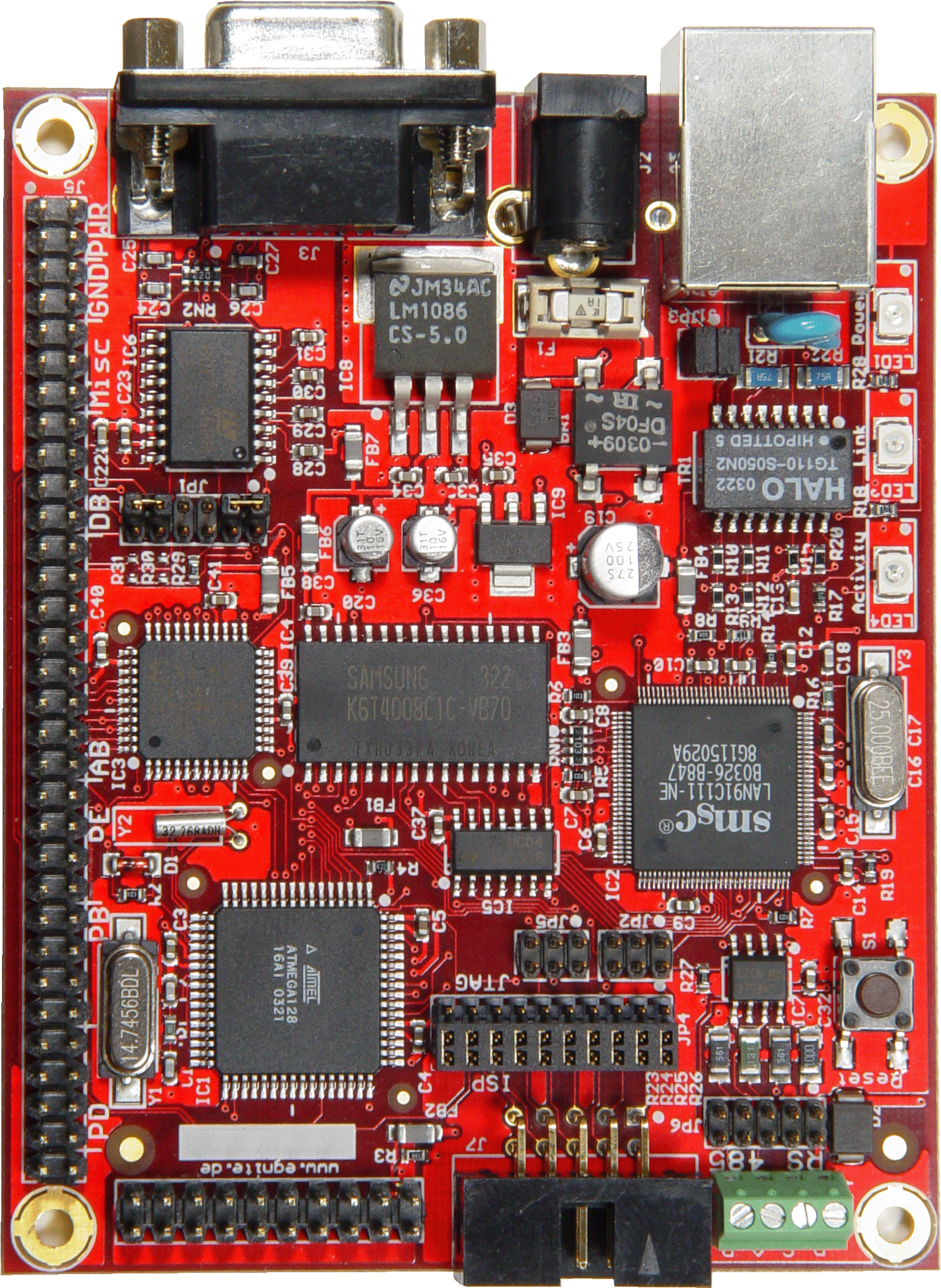
PCB Version 2.1 Revision B
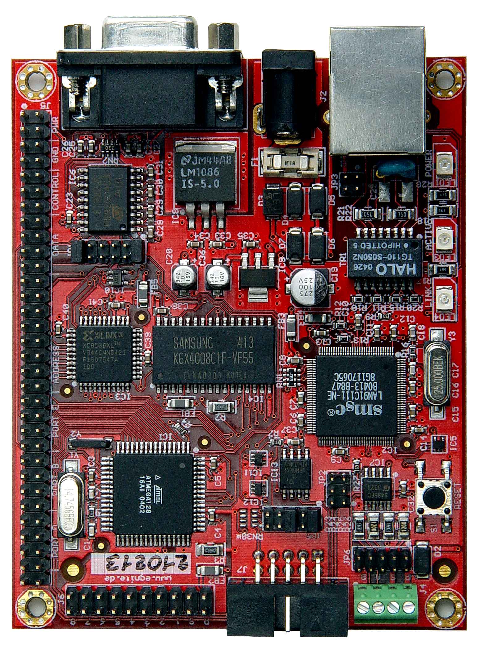
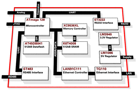
4-layer board with ATmega128 running at 14.7456 MHz, 100 MBit SMSC
Ethernet Controller, 512 kBytes banked SRAM and 512 kBytes serial
flash memory.
Ethernut 2.1 Hardware User's Manual
including all schematics (updated).
Ethernut 2.1 Dimensions (in mm)
Changes since 2.0
- ISP no longer provided, programming is done via JTAG only. Unfortunately Atmel's JTAG and ISP connectors use the same physical dimensions. Make sure to use JTAG programmers with Ethernut 2.1. Plugging in an ISP adapter will blow the on-board fuse.
- 512 kByte data flash AT45DB041 added, selected by PB4. If this conficts with your existing application, IC 12 should be removed to disable the data flash.
- ALE signal can be routed to expansion port pin 64 when mounting optional resistor R34.
- MIC2775 reset controller added.
- Two additional jumpers for isolating CPLD from PORT F.
- Rectifier bridge has been replaced by 4 rectifier diodes.
- Glue logic uses pico gates.
- Ground signal traces simplified, following SMSC's latest advices.
Known Problems with Version 2.1 Rev.-B
-
The board had been tested to run over the full industrial temperature range from -40°C to +85°C (-40°F to +185°F). However, in the field it turned out, that several boards experienced network connection problems at low temperatures. The reason is, that the design of the 3.3V power supply does not follow the recommendations provided in the datasheet of the LM3940. To fix this, the value of C36 had been changed from 10uF to 33uF and C35 had been changed from 100nF ceramic to 10uF low ESR tantalum.
-
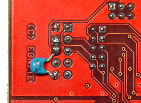
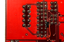
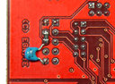 The MIC2775 reset controller is very sensitive. A 10k pullup resistor and
a 100n capacitor to ground had been added to the MR/ (manual reset) line.
In early board revisions they are mounted on the back side of the board at
the JTAG connector. Klick on the photo for a larger view.
The MIC2775 reset controller is very sensitive. A 10k pullup resistor and
a 100n capacitor to ground had been added to the MR/ (manual reset) line.
In early board revisions they are mounted on the back side of the board at
the JTAG connector. Klick on the photo for a larger view.
Initial Software
egnite delivers the boards pre-installed with
- basemon.hex
A simple application, which tests all basic board functions and outputs the results on the RS232 line. See the hardware manual for further details. Basemon runs on all Ethernuts and automatically detects the CPU clock and the Ethernet controller. - apploadbin.zip
The TFTP bootloader for the LAN91C111 Ethernet controller.
More...
appload-1.1.1.zip
Contains a newer version of the Ethernut 2 bootloader.
PCB Version 2.0 Revision A
4-layer board with ATmega128 running at 14.7456 MHz, 100 MBit SMSC
Ethernet Controller and 512 kByte banked SRAM.
Ethernut 2.0 Hardware Manual
including all schematics.
The original Eagle CAD files and the Xilinx schematic are available in the download area.
Known Problems with Version 2.0 Rev.-A
Unfortunately three bugs have been detected recently on all Ethernut 2.0 Rev-A boards. If this is a problem for you, please contact your dealer directly and we will try to help you.
- PF4 and PF5 are hardwired to the CPLD input. This is no problem when using these pins for digital I/O, but may cause problems with analog I/O.
-
PORT F connector GND not connected to R3. This is caused by a major problem
with the
Cad Software we are using. Either use a short wire from the mounting hole or
use a ground
connection on your board.
This has been fixed in the latest production, but you will not visually recognize it, because the modification is done in the inner layer only. -
 Power-on reset of the LAN91C111 requires a minimum raise time, which
is too slow with many power supplies. You can verfiy this using the
Basemon program. When switching on the power supply, Basemon doesn't
detect the LAN91C111. But the chip is detected after pressing the reset
switch on the Ethernut board. After this problem had been discovered,
egnite shipped Ethernuts with an addtional DS1811 mounted on the back side
of the board. You may also mount R31 and use PE7 to hardware reset the
Ethernet controller. Klick on the photo for a larger view.
Power-on reset of the LAN91C111 requires a minimum raise time, which
is too slow with many power supplies. You can verfiy this using the
Basemon program. When switching on the power supply, Basemon doesn't
detect the LAN91C111. But the chip is detected after pressing the reset
switch on the Ethernut board. After this problem had been discovered,
egnite shipped Ethernuts with an addtional DS1811 mounted on the back side
of the board. You may also mount R31 and use PE7 to hardware reset the
Ethernet controller. Klick on the photo for a larger view.
